How do you define a vacuum system?
admin | ارسال شده در |
How do you define a vacuum system?
In basic terms the pressure of a gas is provided by the physical presence (and the movement) of molecules. By reducing the number of molecules and/or their natural tendency to move, the pressure of a gas is reduced. For this explanation, any pressure that is less than normal atmospheric pressure is indicative of a vacuum.
In the world of vacuums, there are significant differences between those at the lower end of the spectrum and those that occupy the higher (i.e. high vacuum) levels. In terms of definitions: vacuums that range between atmospheric pressure and 1 mbar are known as “rough” vacuums, whilst pressures from 1 to 10-3 mbar are known as medium vacuums. Thereafter, the vacuum definitions progress from high to ultra-high vacuums (UHVs) through to extremely high vacuums (XHVs) and range from 10-3 to 10-12 mbar.
How to choose the right vacuum pump for your application
Choosing the right vacuum pump is not an easy undertaking. However, before embarking upon the vacuum simulation process, there is a fundamental truth which needs to be accepted: no single pump will match all your requirements or expectations. Nevertheless, the process (should) start with a clear view of the vacuum range you are trying to obtain, as well as the use to which the vacuum will be put (which in itself will provide an indication of the capacities required). From this basic bedrock of requirements stretches out a further series of “stepping stones” (some significant, others less so) including noise and vibration considerations, ease of maintenance, up-front and on-going costs, the size (i.e. footprint) of the pump itself, its resistance to shock, tolerance to particle intrusion and whether oil contamination would be an issue. By scrutinising this menu of requirements and restrictions, the vacuum engineer ought to be able to hone-in onto the most suitable vacuum pump for the task in hand.
There are a large number of vacuum pumps which cater for the lower (i.e. rough and medium) vacuum range, including the diaphragm pump at one end of the spectrum through to the screw, rotary and roots pumps at the medium vacuum end.
The types of pumps employed for rough and medium vacuums (when compared to high through to XHV pumps) are fairly simple in terms of the vacuum system operation. However, that is not to underestimate the precise engineering required (or indeed the science) behind their workings. Furthermore, it should not be forgotten that many of these pumps are employed as fore (or backing) pumps, which are employed to “charge” higher level vacuum pumps. Without the benefit of such fore-pumps, these higher vacuum units would at best – operate sluggishly and slowly, and at worst – not at all.
Diaphragm pumps, which operate from 103 to 1 mbar, employ a rod which oscillates backwards and forwards compressing the gas contained within a flexible pipe/chamber. This oscillation activates (alternatively) either an inlet or an exit valve.
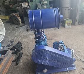
Roots pumps employ two counter-rotating, interconnecting units rotating within a chamber. Gas enters through the intake flange and is “pinched” between the two rapidly rotating units and the chamber wall, and is then expelled through the exhaust port.
Scroll pumps use two inter-wound Archimedean spiral-shaped scrolls (one fixed, whilst the other orbits eccentrically) to pump or compress liquids/gases. Scroll pumps are used where clean, dry vacuum pumping is required.
Rotary vane pumps work in the following manner: an offset rotor (fitted with vanes that slide in and out of their housing) rotates within a chamber. The vanes, which seal against the inside of the circular chamber, “trap” in a quantity of gas which enters through an inlet port. As the rotor rotates, the volume contained between the vanes and the inside surface of the chamber decreases, so the pressure of the “captured” gas likewise decreases, until it exits through the outlet port.
Screw pumps employ two screw rotors which are engineered to rotate “in on each other”, thereby trapping the gas in the void between the “screws” of their rotors. As they rotate, the void between the screws decreases which not only compresses the gas, but also forces it towards the exit portal.
High & Extremely-High Vacuum Pumps
The high-vacuum, UHV and XHV range of pumps are by-and-large dominated by four completely different genres: the turbomolecular pump, the ion getter pump, the cryo pump and the diffusion pump.
Turbomolecular pumps use a very fast spinning rotor not dissimilar to a multi-bladed turbine. The high-speed impact of blades directly onto gas molecules “directs” these molecules towards the “exit” part of the chamber.
Ion getter pumps are effectively repeat units of penning cells sustaining a plasma discharge. Once initiated the discharge. A high potential accelerates the electron toward an anode, but a high magnetic field causes a spiral motion. A dense electron cloud becomes trapped in the anode cylinder. Many ionizing collisions occur with gas molecules. The positive ions are attracted toward the cathode where they can become embedded and causes a sputtering of titanium from the cathode. This active layer pumps molecules by gettering.
Cryo pumps either condense or absorb gases within a three-stage, but two-part vacuum chamber; there are no moving parts. The vacuum is acquired using low-temperatures, provided by a dual-stage cold head. The two functions (condensation and adsorption) operate in parallel.
Diffusion pumps use a directed high speed vapour jet to direct gas molecules in the pump throat down into the bottom of the pump and out to the exhaust. They were named because the design was based on the fact that gas cannot diffuse against the vapor jet, but will be carried with it to the exhaust.
Interested in learning more about the different vacuum pumping technologies? Then why not download our eBook:
Vacuum System Simulation & Design
Choosing the right vacuum pump, may seem like a daunting (long-winded and costly) exercise–which is where engineering simulation comes in. By putting values to each uncertainty and sign-posting every decision node, simulation has taken much of the wasteful cost and iterative guesswork out of what has traditionally been the tortuous process of vacuum pump and vacuum simulation.
Engineering simulation (or modelling) is a well-established practice and methodology whereby a substitute for physical experimentation is created, allowing mathematical values to be calculated and then employed to describe how a system and/or a process may (or may not) perform.
This table-top, computer assisted exercise is conducted before any components are purchased, and before the system/process path and sequence have been confirmed. In its simplest terms, simulation/modelling can identify problems and anomalies in the design stage, thus eliminating the orthodox but out-dated and wasteful “design-build-test-redesign” cycle.
The technical characteristics of the various components of a system (that may be employed) are put together into a “trial” system, and a simulated performance is then computer-run to ascertain a number of parameters, including whether: the components are compatible; the system produces the required outcome; the entity operates safely; the results are reliable/repeatable; and if component substitution could produce better results. Furthermore, simulation can highlight any weaknesses (either in components or configurations), as well as providing an indication of any process/system.
The Challenges & Implications of Vacuum Simulation and Operation
The major advantage of engineering simulation is that all this (pre-work) can be carried out without having to go to the expense of actually purchasing expensive components (which may prove to be unsuitable or redundant) or, indeed, having to engineer/assemble the system at this embryonic stage.
It must be appreciated that vacuum simulation is not without its drawbacks.
Vacuum simulation calculations assume that the system is in a steady state. However, whilst such steady state simulation is fast, stable and accurate for simple system models, it fails to account for the misconception that throughput is in fact not constant throughout the system. In simple cases this disparity creates an acceptably small error, but in more complex systems, the error can be significant. Additionally, such “steady state models” are not suitable for systems with dynamic pumps, or for primary pumps/secondary booster combinations, which slow down at high-inlet pressures.
Furthermore, it must be appreciated that, as with many procedures, there is never a true substitute for “the real thing”. Whilst simulation will – at the very least- “shave off” some of the imperfections of a system or poor/incompatible item choices, there is really no cast iron guarantee that additional refinements or re-engineering of components and processes will not further perfect the final system.
Need help with your vacuum simulation project? Get in touch with our experts today for a free no-obligation consultation:
Vacuum Simulation Tools
There are a number of specialist simulation software tools available to the vacuum fraternity.
PumpCalc is a simulation package for “simple systems” (i.e. those that consist of a chamber, a foreline and a pump set), with the “pressure” time from pump output to the chamber being small enough so that speed and conductance are approximately constant. Whilst PumpCalc is best suited for simple systems, it can still be used on more complex systems, if symmetry can be used to simplify the entirety.
TransCalc is a network-based computational simulation software package for the design of vacuum systems. TransCalc is based upon duct-flow prediction techniques which provide a solution across all pressure ranges (including turbulent, compressable and transitional flow). Compared to steady-state models, TransCalc uses fewer primary assumptions about the system, calculates pipe flows based on whole-system throughput and, furthermore, modifies pressures by conserving throughput over a short time interval.
Pascal is a smart simulation tool enables the engineering of a flow-optimisation pump system using empirical data gained from existing pumps, which is coupled with data from the components required to complete the vacuum system, and then through simulation allows the study of three-dimensional molecular flow through the whole unit. Then, by using existing CAD data the simulation software can calculate the characteristics of the entire vacuum system, allowing flow engineering to be optimised.
MolFlow is a Monte-Carlo simulator package developed at CERN, which provides insight into the behaviour of vacuum systems. MolFlow can show the distribution of the number of gas bounces, the flight distance and the flight time of test particles.
VacSim is a PC-based software simulation package which uses the hermetic capture of a vacuum system and is able to predict/calculate how the system pressure varies with time, throughput volumes, pump speed and oil back-streaming. VacSim is able to produce pump-down curves, show the impact of bakeout regimes, illustrate the impact of (construction) material and demonstrate what difference a pump change will make.
VacSim is perhaps not as sophisticated as some vacuum simulation packages but makes up for this by its inherent simplicity and its ease-of-use.
COMSOL can trace its development from 1986 at the Royal Institute of Technology in Stockholm, Sweden. It is used for vacuum system simulation including those used in semi-conductor processing, particle acceleration and mass spectrometers. Small channel applications (such as shale gas exploration and gas flow in nano-porous materials) can also be simulated.
ANSYS is a stress analysis CAD-type finite element (FE) analysis software package that provides a multi-coloured graphic image that can assist in the balancing of rotors, seismic simulation, model analysis, non-linear stress (i.e. creep and/or fatigue modelling), all of which are important in ensuring product reliability and safety. In addition to traditional stress analysis, ANSYS also has a thermal capability that provides a visual model of thermal distortion in pump components, evaluates cooling (thus highlighting cool spots which can lead to condensation), and enables multi-physics modelling (by coupling stress and magnetic analysis).

